NanoDLP Shield V1.1
Product Introduction
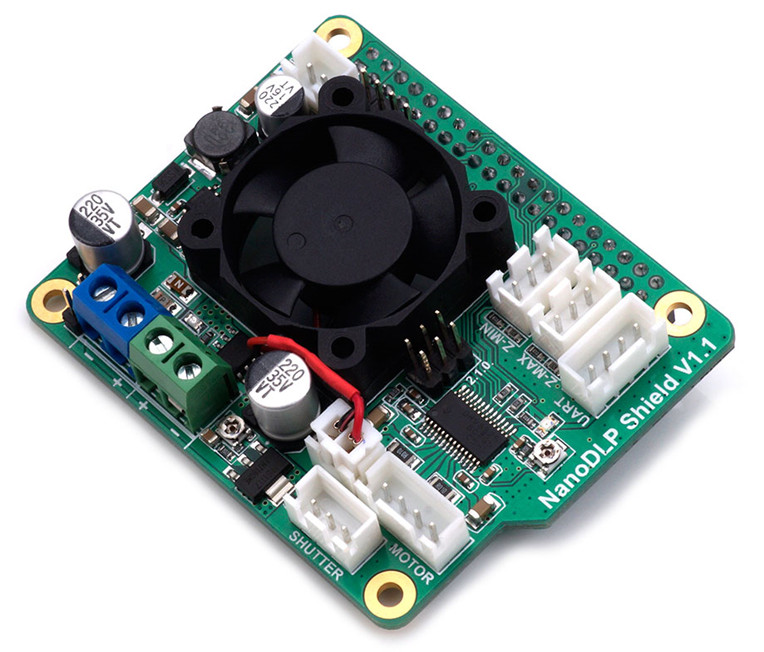
This expansion board is designed for the Raspberry Pi 3B which is used for SLA/DLP 3D printers running NanoDLP . The board contains a 9-28V to 5V circuit that provides a maximum of 3A and other interfaces required by NanoDLP. See the instructions below.
Features
- 9V-28V to 5V@3A Buck Converter
- DRV8825 Stepper Driver
- 12V Fans (cooling the Pi)
- 2X Endstops
- Controled MOS for ext LED driver
- I2C Connector for LCD1602
- Uart Connector for Touch Screen
- Shutter support
- 5V OUT Connector for ext Board
Application
- For NanoDLP software on Raspberry Pi
Specifications
| Board Name | NanoDLP Shield |
|---|---|
| License | CPL V2 |
| Latest Version | V1.1 |
| Fixed Port | 1X 12V(Same as input) and 5V |
| Controlled Port | 1X 12V(Same as input) |
| Endstops | Z-min /Z-max |
| I2C | 1X PinHeader-4P |
| Serial port | 1X XH2.54-4P |
| Stepper driver | 1X DRV8825@2.5A max/32 microsteps max |
| Input | 9V-28V |
| Output | 5V@3A max, 9-28V@3A max |
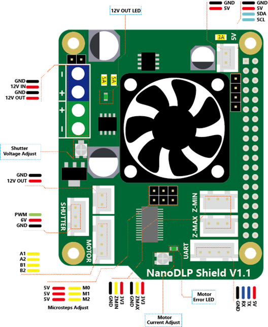
Interface Resources
Interface Layout
Micro-stepping
Shorted = 1, Open = 0 .
| MS2 | MS1 | MS0 | Microsteps |
|---|---|---|---|
| 0 | 0 | 0 | Full step (2-phase excitation) with 71% current |
| 0 | 0 | 1 | ½ step (1-2 phase excitation) |
| 0 | 1 | 0 | ¼ step (W1-2 phase excitation) |
| 0 | 1 | 1 | 8 microsteps/step |
| 1 | 0 | 0 | 16 microsteps/step |
| 1 | 0 | 1 | 32 microsteps/step |
| 1 | 1 | 0 | 32 microsteps/step |
| 1 | 1 | 1 | 32 microsteps/step |
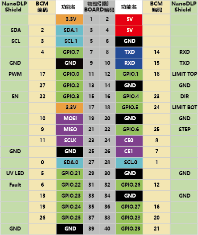
Pin Definition
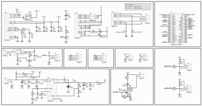
Schematic
Wiring Diagram
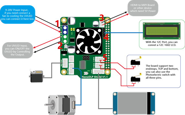
- 9-28V Power Input, if you need connect a fan to cooling the UVLED you can connect it here too.
- For UVLED Input, you can ON/OFF the UVLED by Controlling the Output.
- HDMI to MIPI Board or other device which need 5V power.
- With the I2C Port, you can connet a I2C 1602LCD.
- The board support two endstops, TOP and bottom, you can also use the Photoelectric switch with all three pins.
Shop
Tech Support
Please submit any technical issue into our forum