SB CAN TH
1. Introduction
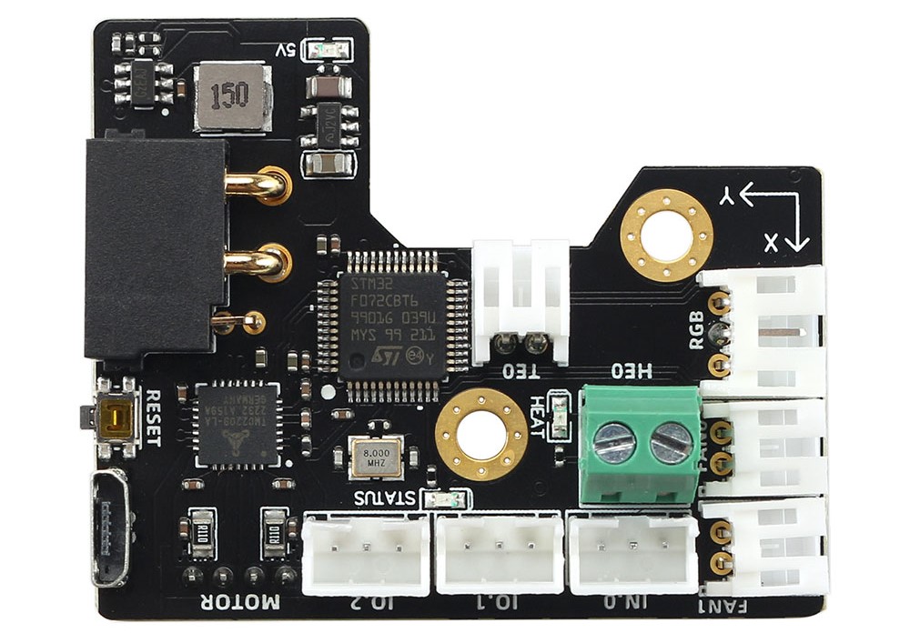
The SB CAN Tool Board is a highly integrated printhead control board. Based on STM32F072, running Klipper firmware. Onboard TMC2209 stepper motor driver, AXL345 acceleration sensor, and other necessary interfaces. And comes with a 2.5m 4-core cable for easy out-of-the-box use.
1.1 Feature
-
Based on STM32F072
-
Onboard 1M CAN transceiver
-
Onboard TMC2209
-
2x 0.5A MAX PWM interface for controllable fan (default VIN power supply, 5V optional)
-
1x signal input interface (VIN power supply, with level conversion)
-
2x signal input and output interface (5V power supply, with pull-up resistor)
-
1X 5V single wire RGB interface (1A MAX)
-
1x 4A MAX PWM output for heating rod
-
1x ADC interface for heating rod temperature acquisition
-
MX3.0 2X2 interface for power and CAN signal access
-
1x Micro USB for firmware uploading
-
Comes with 2.5m 4-core cable, 2x16AWG+2x24AWG
-
Comes with terminal housing and wire crimping tabs
2. Hardware Guide
2.1 Install
Before you install the board, you need printed parts here. Then follow the 5 steps below.

- You Stealburner should have to holes with heat inserts on.
- 3D Print the pcb_spacer.STL
- Place the PCB on the position
- Screw it to printed head and pcb_spacer.STL
- Follow the chapter
2.2 wiringto connect the peripherals and cover the lid.
2.2 Connectors
| Connector name | Type | Details |
|---|---|---|
| IO.2 | PH2.0-3P | PB7,for input and output, hardware pull-up 10k resistor to 3.3v with 1k series resistor. Example: endstops |
| IO.1 | PH2.0-3P | PB11,for input and output, hardware pull-up 10k resistor to 3.3v with 1k series resistor. Example: endstops |
| IN.0 | PH2.0-3P | PB6,default 24v with level translator, pull-up to 3.3v |
| MOTOR | PH2.0-4P | TMC2209 EN : PB4 DIR : PA5 STEP : PA7 SPREAD : PA15 DIAG : PB5 INDEX : PB3 RX : PA10 TX : PA9 |
| INPUT | MX3.0 2X2P | Max 24v 5A input(16AWG)/CANL,CANH (24AWG) |
| TE0 | PH2.0-2P | PA0,ADC,4.7K pull-up to 3.3V |
| HE0 | XH2.54-2P | PA8,MAX 4A,PWM output,max power recommended: 60W |
| FAN0 | PH2.0-2P | PA2,0.5A MAX PWM,for fan control (default VIN,5V selectable) |
| FAN1 | PH2.0-2P | PA3,0.5A MAX PWM,for fan control ( defalt VIN,5V selectable ) |
| RGB | PH2.0-3P | PB1,1A MAX sigal line RGB port, 5V,for NeoPixel, WS2812 |
| Micro-USB | For firmware update and USB communication. Firmware update: Plug in USB first then power on. USB communication: Power on first then plug in USB port |
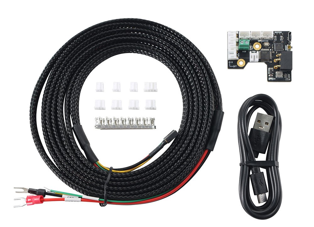
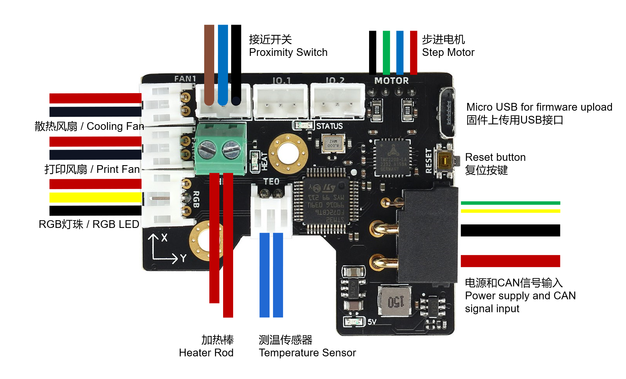
2.3 Wiring
As shown below, you receive not only a SB CAN Tollhead Board, but also a 2.5-meter connector and some connectors and a USB cable.
V1.1


V1.3
Note
Klipper currently supports the USB to CAN Bridge mode of the motherboard. You can use the motherboard as a CAN adapter on the Raspberry Pi, no longer requiring UCAN.
2.4 SCH DXF STEP
Get SCH, DXF, STEP files on github:
GitHub - FYSETC/FYSETC_SB_CAN_TOOLHEAD: StealthBurner toolhead CAN bus module for VORON
3. Firmware Guide
This is only Klipper firmware support. If you are Klipper beginner please check the Klipper firmware build here: Installation - Klipper documentation
3.1 menuconfig

3.2 Firmware Upload
Danger
Do not hot-swap 24V, as there is a certain probability of damaging the 5A fuse on the board. You can plug in the 24V socket of the SB CAN ToolHead, and then switch the 24V power supply on and off from the power supply! For the V1.3 version, just plug in the USB cable and press the reset button. There is no need to re-power on the 24V!
For V1.1
There is Micro-USB port on the board for firmware upload. Follow the sequence below.
-
Connect SB-CAN-TH Micro-USB to Raspberry Pi USB-A port with USB cable
-
Plug in SB-CAN-TH board 24v socket to the machine PSU
-
Power on your raspberrypi (Or other SBC) and wait it boot ready.
-
Power on the 24v PSU for SB-CAN-TH board
-
Shoot
lsusbcommand in Raspberry to check if it shows DFU port, if not go back to step 1 -
Shoot command
dfu-util -R -a 0 -s 0x08000000:leave -D out/klipper.bin -
Remove Micro-USB cable and SB-CAN-TH socket for 5s, then plug in SB-CAN-TH socket again.
-
Finished
For V1.3
There is Micro-USB port on the board for firmware upload. and a reset button for mcu reset , Follow the sequence below.
- Connect SB-CAN-TH Micro-USB to Raspberry Pi USB-A port with USB cable
- Plug in SB-CAN-TH board 24v socket to the machine PSU
- Power on your raspberry pi (Or other SBC) and PSU , wait the pi boot ready.
- hold reset button for 2 seconds, then release it
- Shoot
lsusbcommand in Raspberry to check if it shows DFU port, if not go back to step 1 - Shoot command
dfu-util -R -a 0 -s 0x08000000:leave -D out/klipper.bin - Remove Micro-USB cable and SB-CAN-TH socket for 5s, then plug in SB-CAN-TH socket again.
- Finished
3.3 Configuration
Obtain the Klipper configuration file here , you need to get the CAN ID following CANBUS - Klipper documentation:
4. Log and known issues
4.1 v1.1
Note: v1.1 have some silk print errors below, the red letters are the right silk print.

4.2 what new in v1.3
- Changed the connector and connecting wire that can carry a maximum current of 15A (the onboard fuse is limited to 8A);
- Add a reset button;
- Change to a 6-layer 2OZ PCB board to enhance heat dissipation;
- Add a 120R termination resistor, which can be disconnected through JP3 and is connected by default;
- Change the heating rod connector to carry larger current, up to 7A;
Buy
Contacts
QQ:1041794121
Facebook小组:https://www.facebook.com/groups/197476557529090
Discord频道:https://discord.gg/Fb6FdND4