2.1 Frame assembly
2.1 Frame assembly
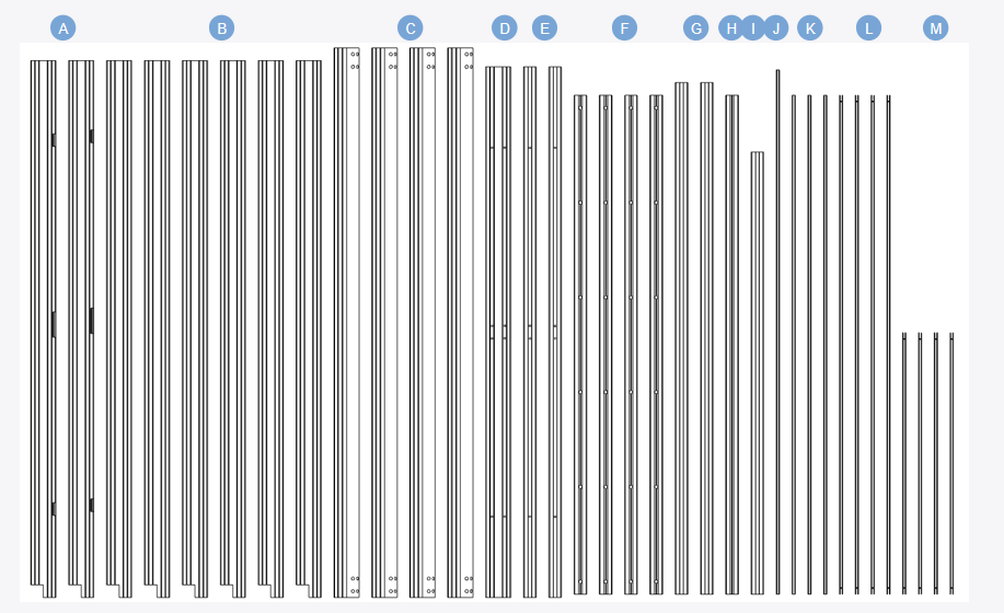
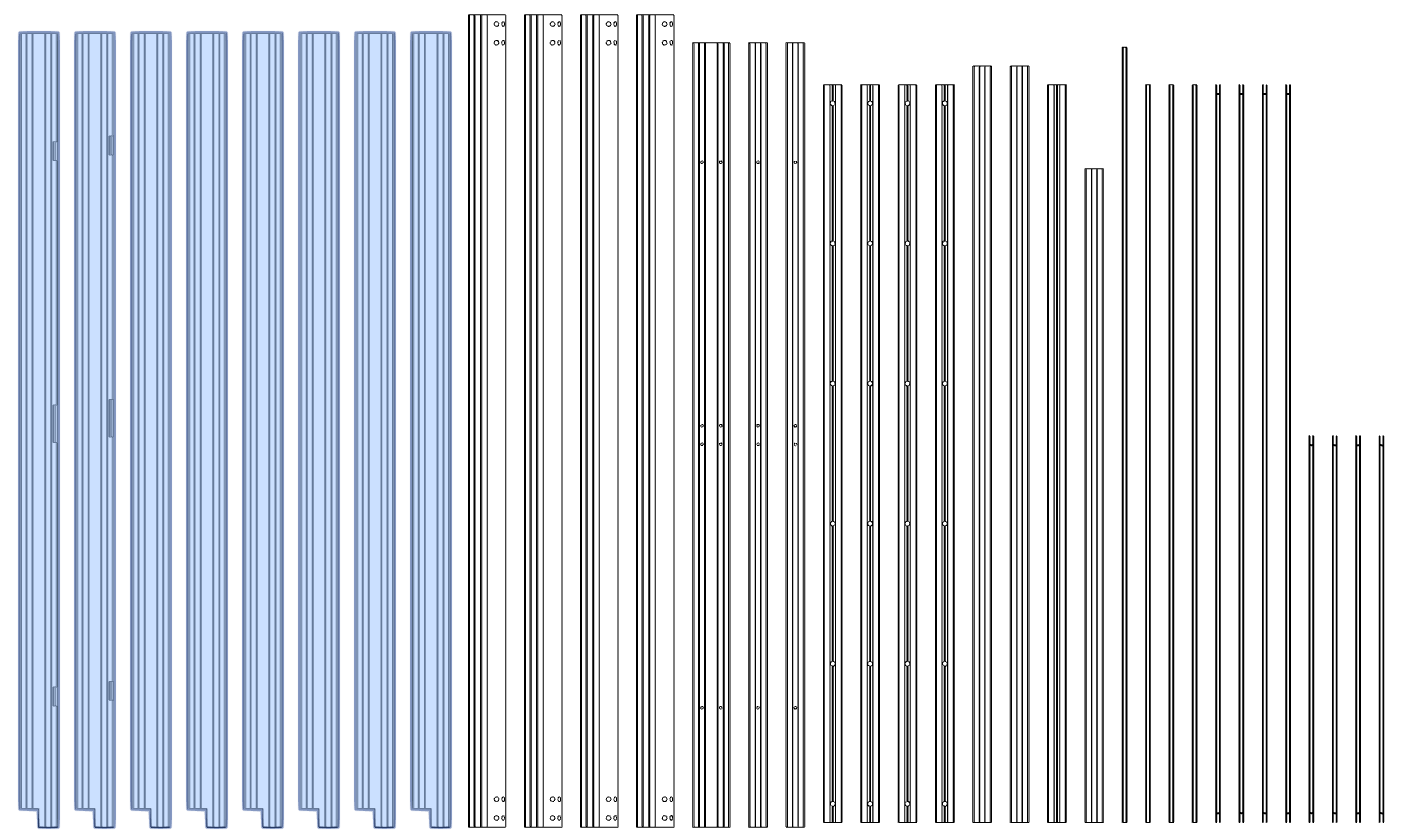
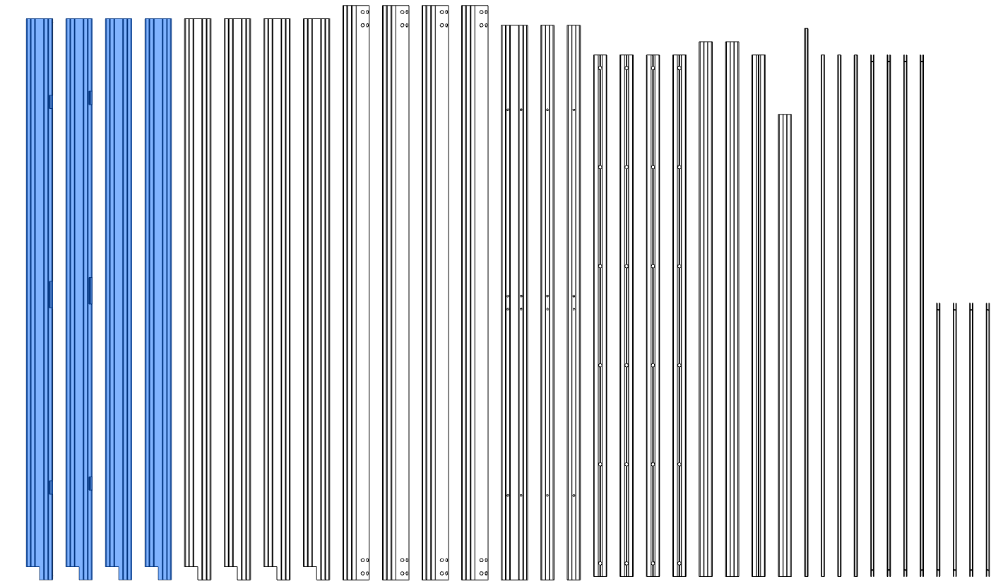
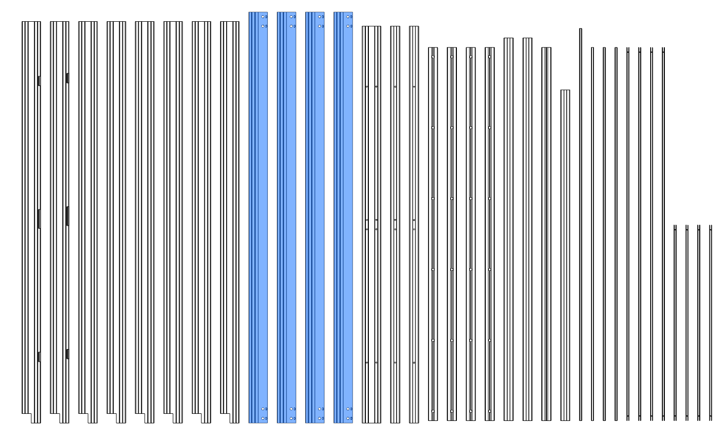
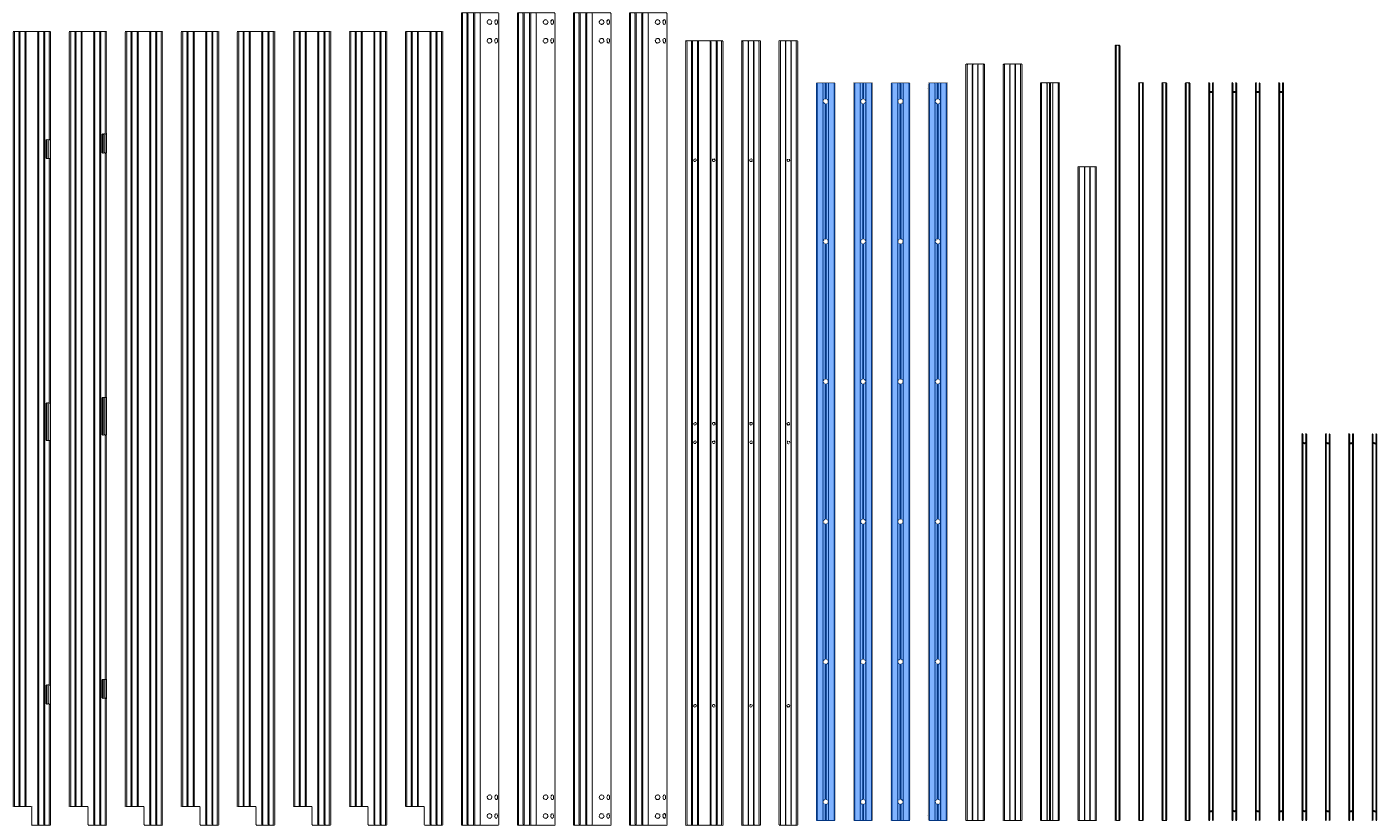
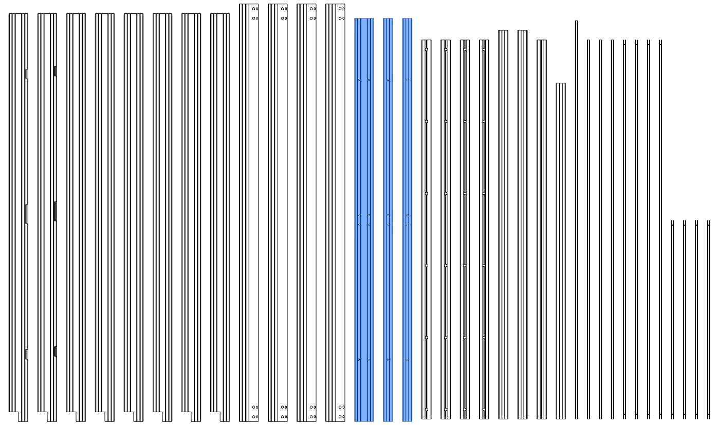
Material preparation
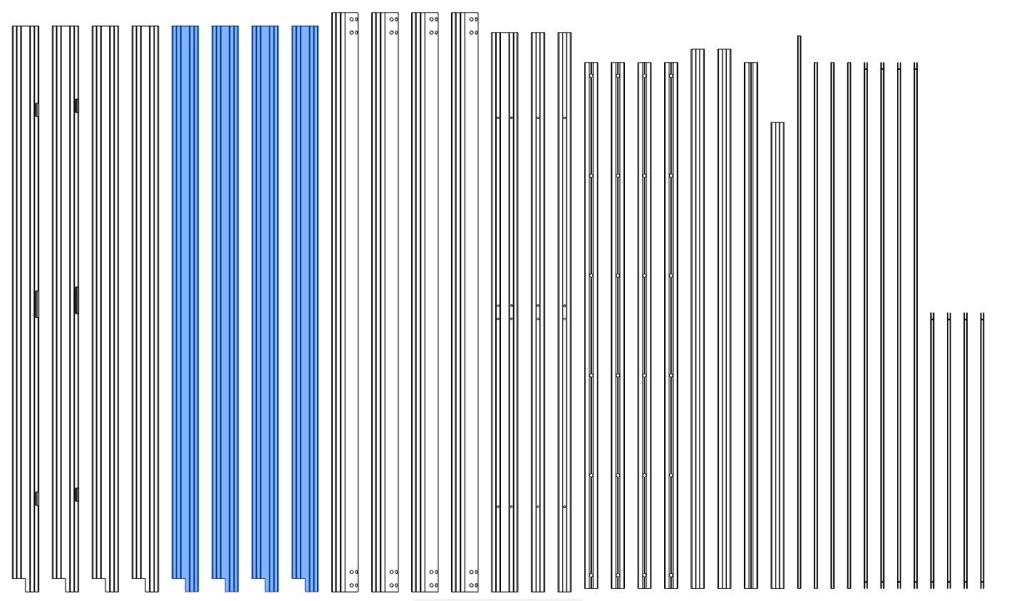
- Sort extrusions,collect your extrusions and sort them by length. We will highlight the
- extrusions used in each step and label them as shown on this page.
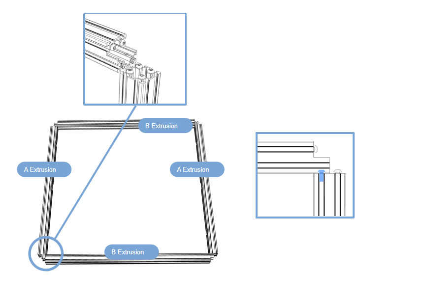
2.1.1 Bottom and top frame assembly
-
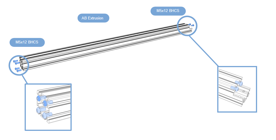
Prepare the first 8 aluminum profiles that will be used in this section;
-
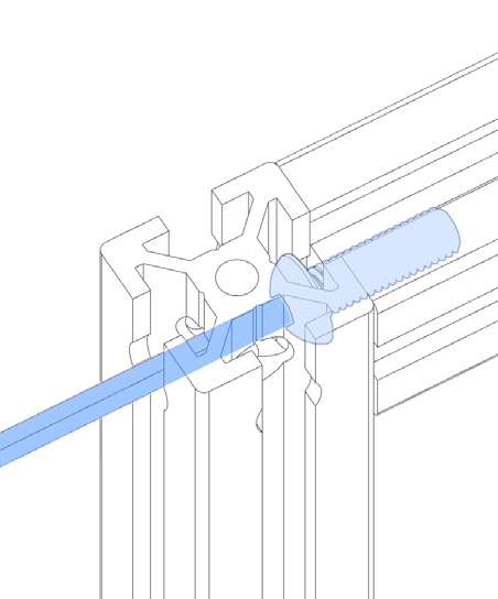
Prepare them as shown above, screw the 6Pcs M5x12 BHCS into the aluminum profile, do not tighten.
Top of frame
-
Prepare the first 4 aluminum profiles that will be used in this section;
-
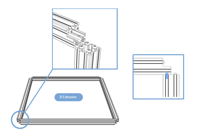
Build the frame on a flat surface(build the frame on glass or granite surface) to ensure you get as flat and square a frame as possible;Take out the 4 pieces shown in the picture from the 8 profiles assembled earlier, connect them end to end, with the end faces facing outwards, and tighten the screws.
Bottom of frame
-
Prepare the first 4 aluminum profiles that will be used in this section;
-
Build the frame on a flat surface(build the frame on glass or granite surface) to ensure you get as flat and square a frame as possible;Take out the 4 pieces shown in the picture from the 8 profiles assembled earlier, connect them end to end, with the end faces facing outwards, and tighten the screws.Repeat the previous work.
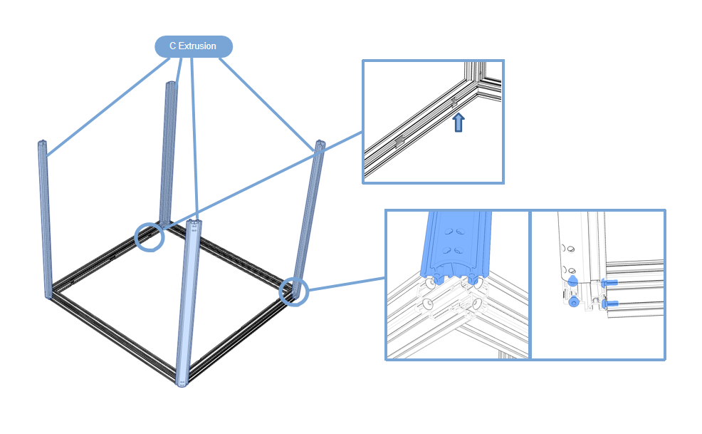
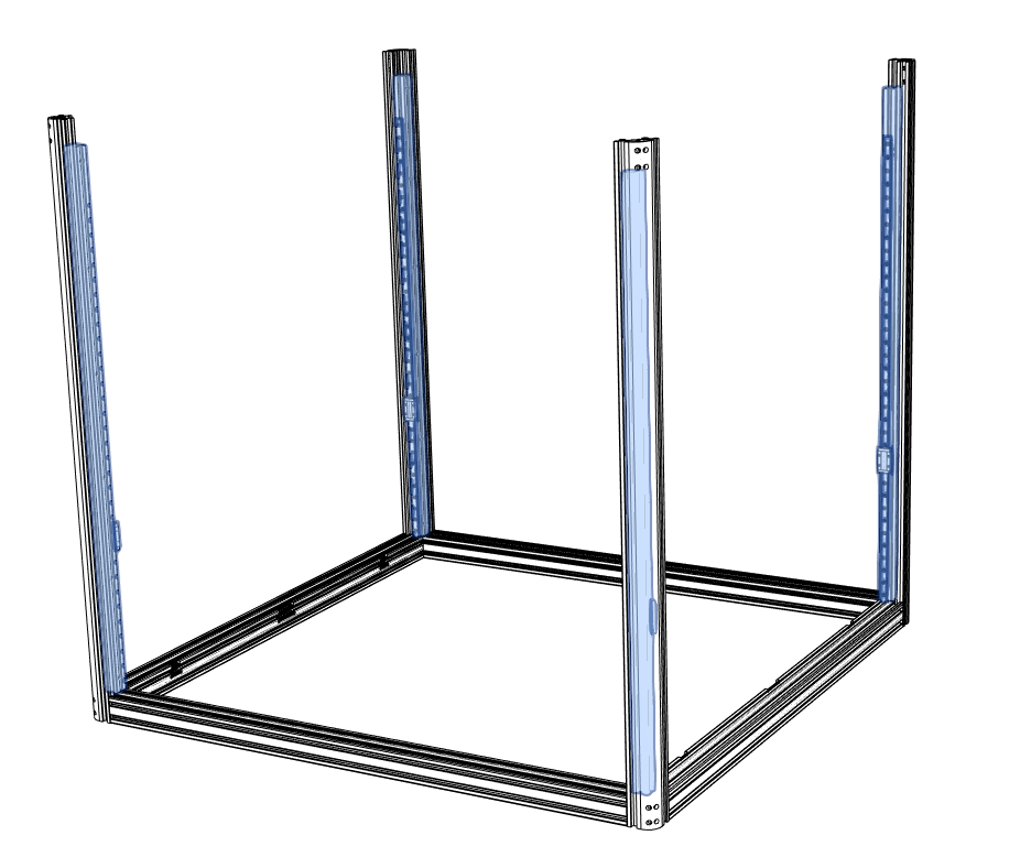
2.1.2 Frame column
-
Prepare the first 4 aluminum profiles that will be used in this section;
-
Build the frame on a flat surface(build the frame on glass or granite surface) ,Take out the 4 aluminum profiles shown in the picture and insert them into the assembled profile base from top to bottom;
The notch of the bottom assembled profile faces upward, the arc surface of the four columns faces outward, and tighten the screws.
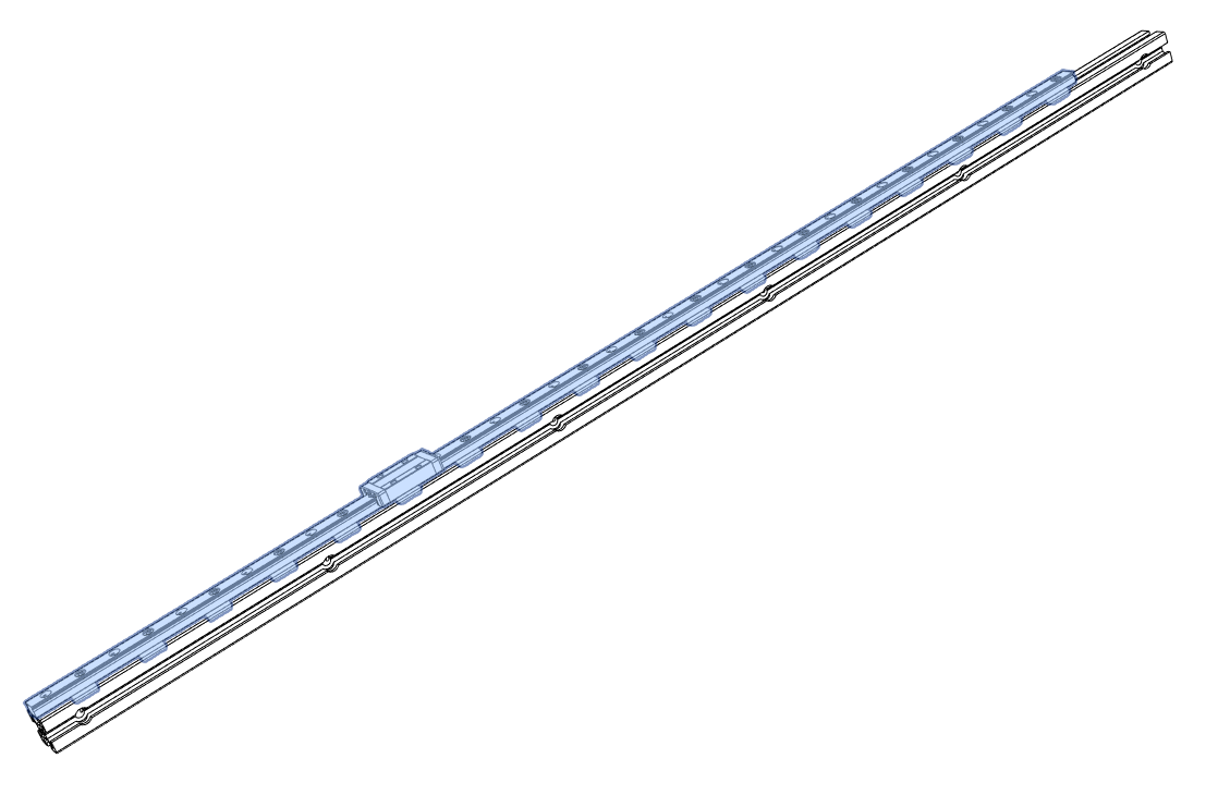
2.1.3 Z-axis guide rail
-
HANDLE WITH CARE
The carriage can slide off the rail if not handled properly. Dropping the carriage will likely damage it.Any marks, dents or nicks might cause the linear rail to misbehave in operation.
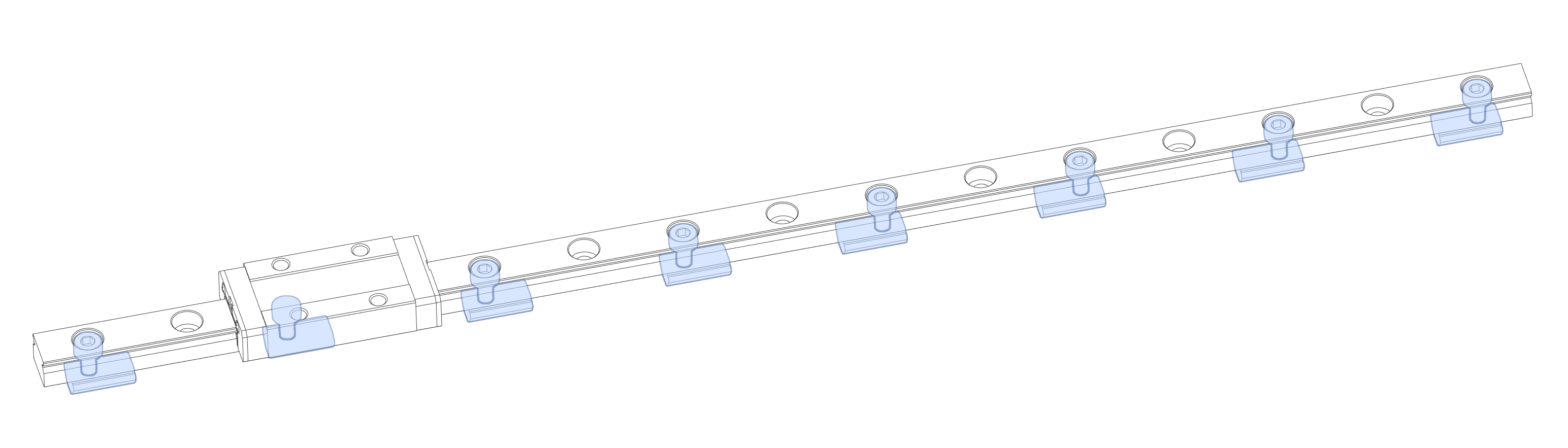
Use SHCS M3x8 and M3 T-Nut, install them on the rail at intervals, and do not tighten the M3 T-Nut
We opted to skip every other mounting hole in the linear rail when designing the mounting pattern for this printer. This cuts down on mounting hardware and still meets the requirements for our use case.When tightening the bolts tighten them from the center outward to ensure that the rail sits flush on the extrusion.
-
Prepare the first 4 aluminum profiles that will be used in this section;
-
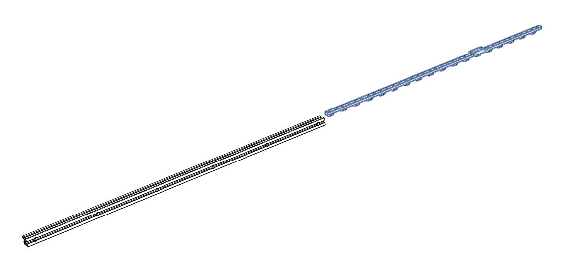
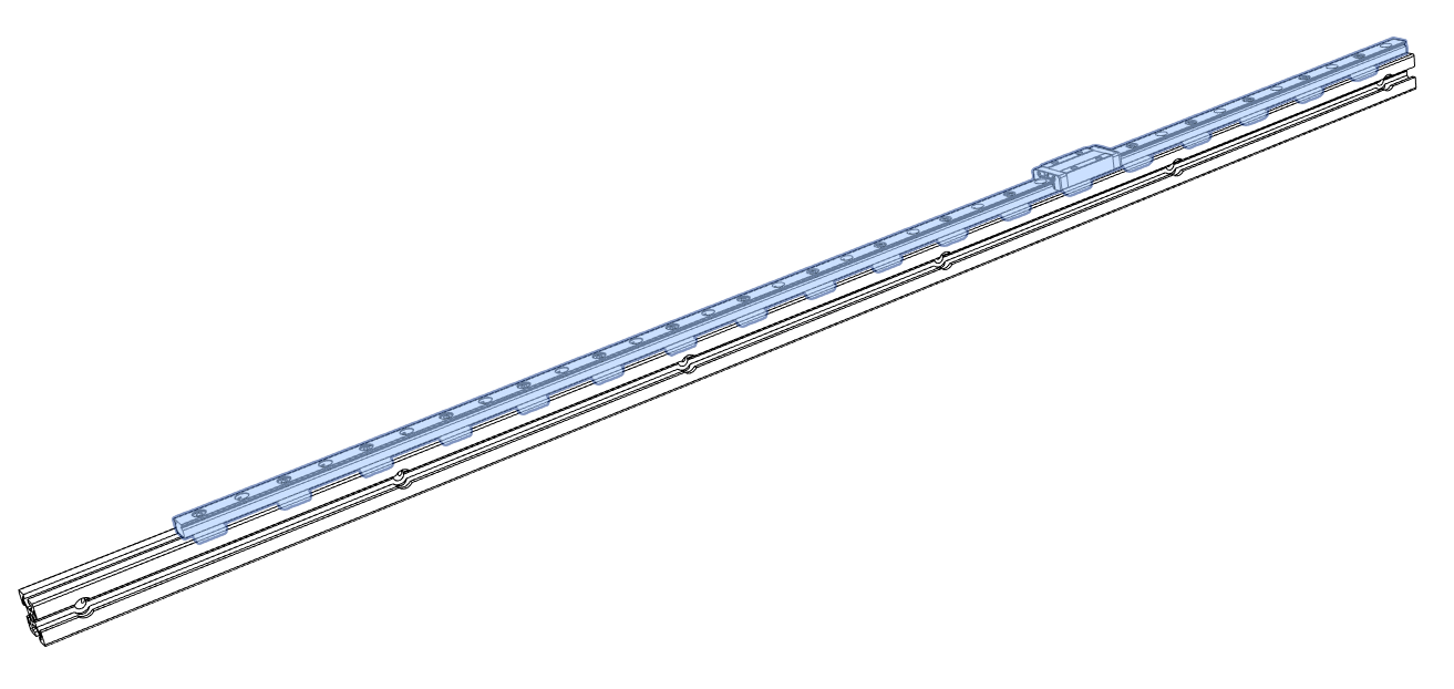
Install the assembled guide rail onto the aluminum profile above.Carefully insert from one end of the profile
-
Assemble 4pcs in sequence, assemble according to the picture below (one end faces the end of the profile), 2pcs each.One end of the guide rail is flush with the profile
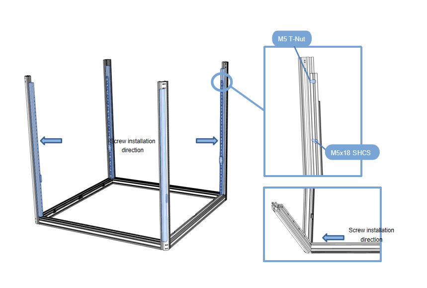
2.1.4 Z-axis rail assembly installation
-
First install the M5 T-Nut on the 2020R profile. Install the parts assembled in step ④ onto the frame in step ③,flush side facing down.
-
Be careful not to let the guide rail slide fall off!
-
Take out the 4 aluminum profiles shown in the picture, place them on the base, and tighten the screws.
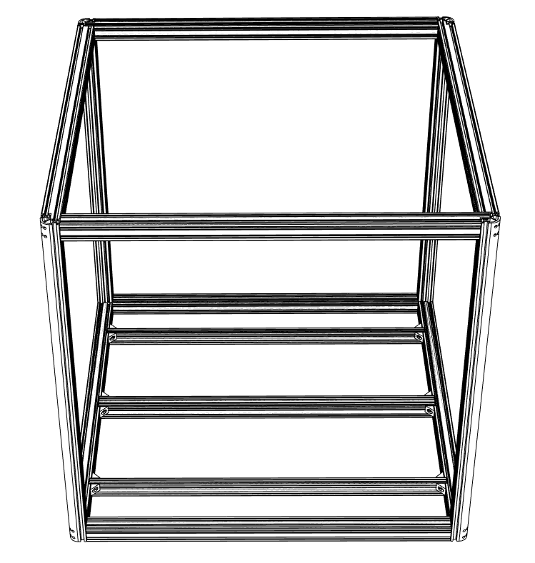
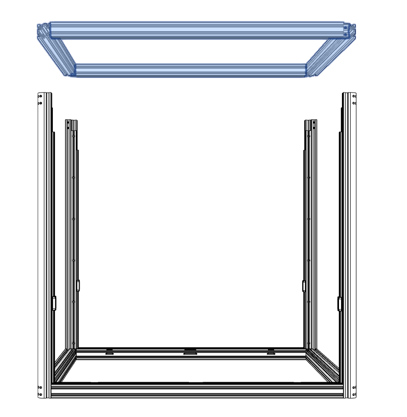
2.1.5 Top profile assembly
- Install the previously assembled frame ② on the upper part, seal the top, and tighten it with screws from the holes around it.
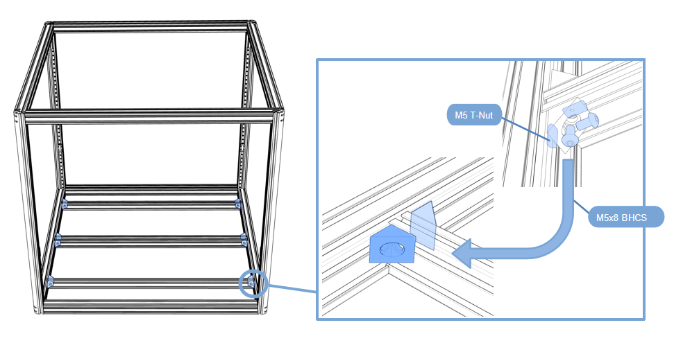
2.1.6 Hot bed support profile installation
-
Prepare the first 4 aluminum profiles that will be used in this section;
-
Install the printing platform support profile at the bottom, 2040 on both sides and 4040 in the middle. Pay attention to the gap in the profile.
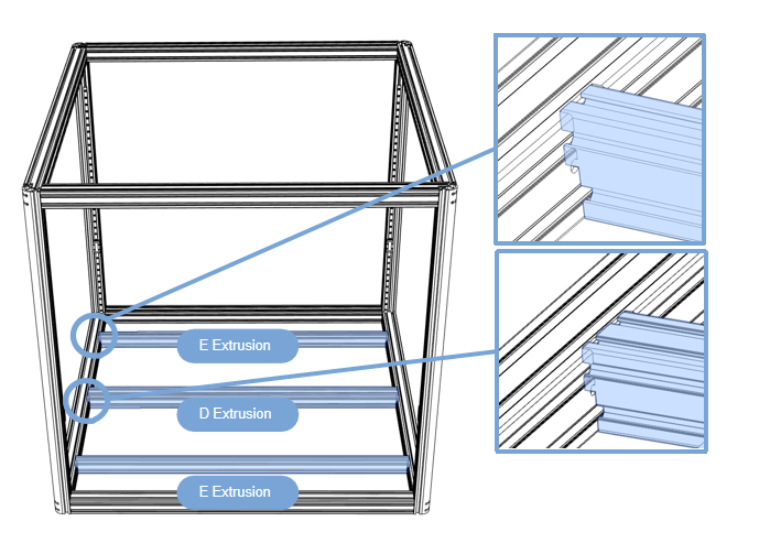
-
First put the M5 T-Nut into the profile,Use M5x8 screws and angle brackets to fix on both sides (2040 on both sides and 4040 in the middle, pay attention to the gap in the profile).