Search...
Menu
2.2 Z motor and tensioner assembly
Download
2.1 Z motor and tensioner assembly
2.1.1 Z tensioner assembly
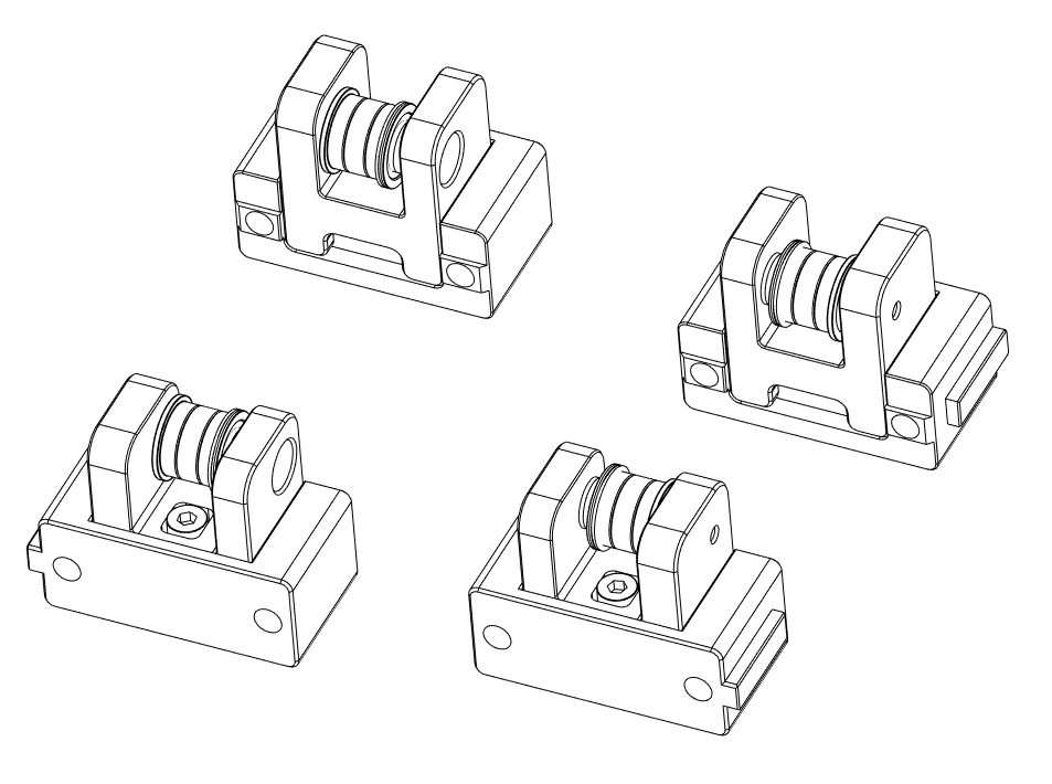
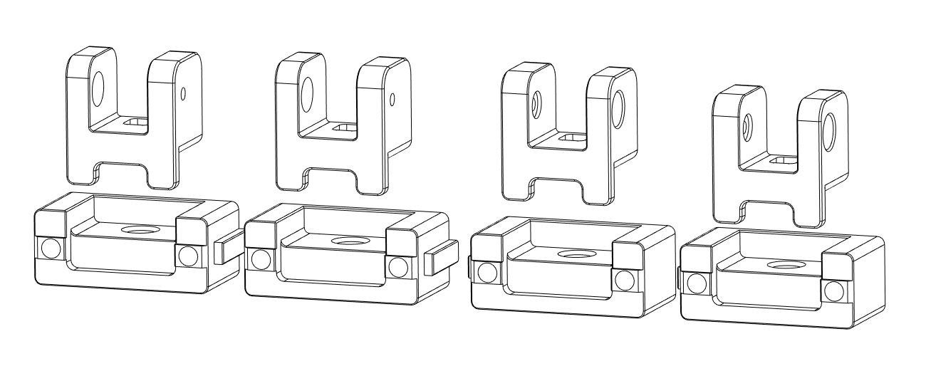
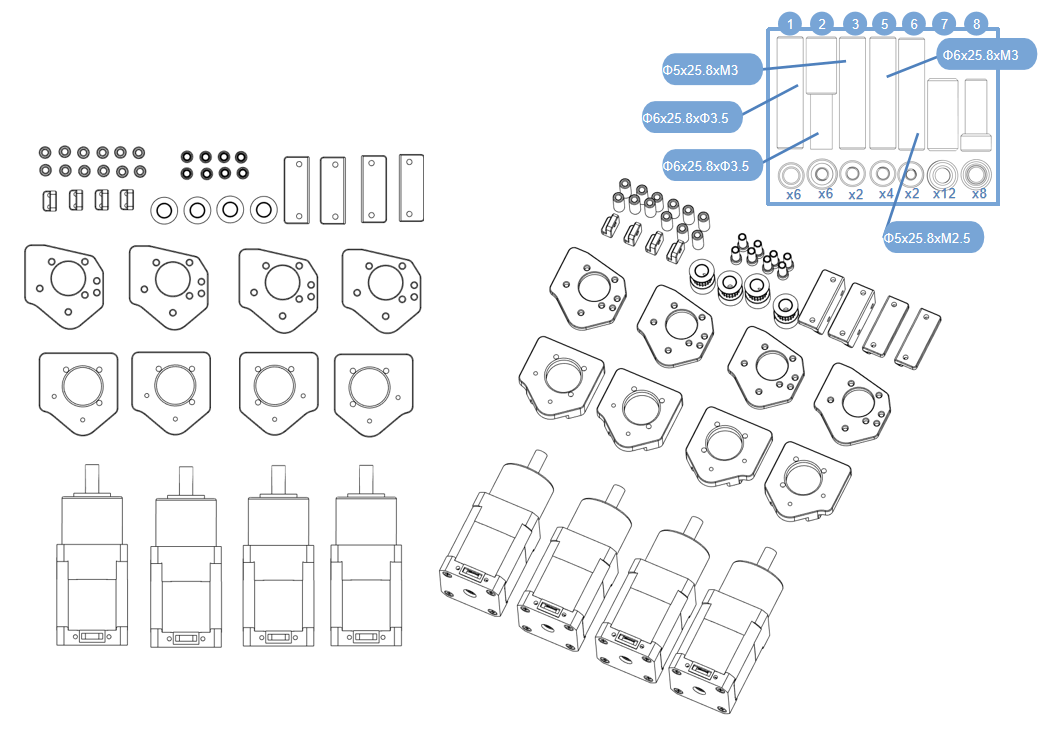
- Material preparation
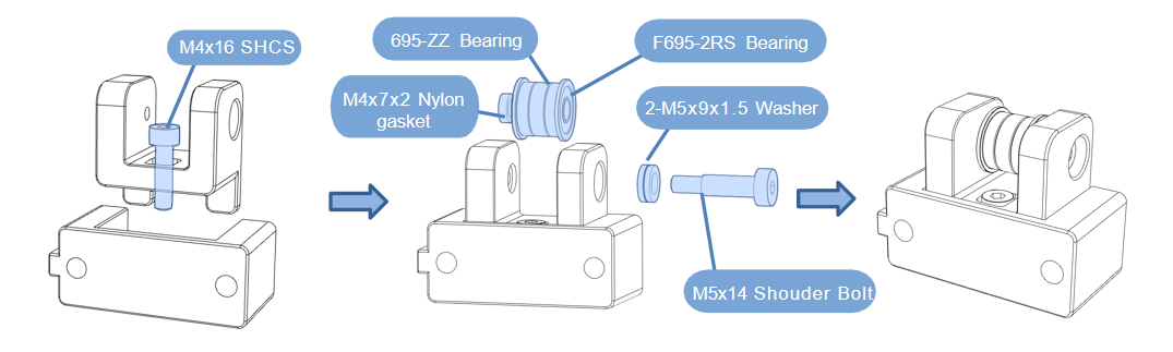
Z tensioner assembly-Right
- Take out the CNC parts as shown in the figure, first use “SHCS M4x16” to fix it, and then use “Shouder Bolt M5x14” to fix it through the bearing, as shown in the figure.Quantity:2 Pcs.
Z tensioner assembly-Lift
- Repeat the above steps.Quantity:x2 Pcs.
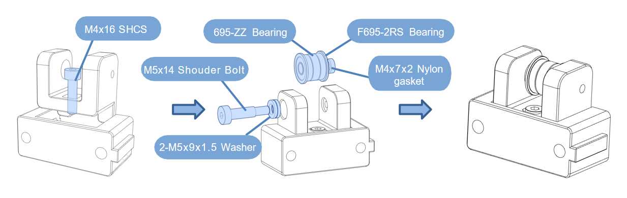
NOTE: The bearing can be replaced with a timing belt idler pulley.
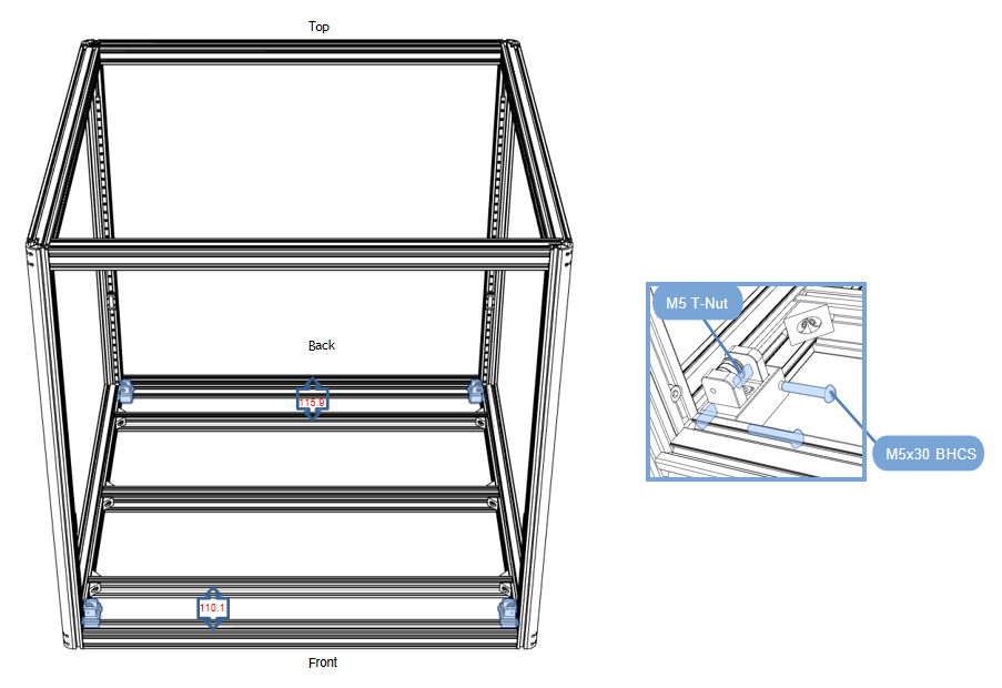
Z tensioner assembly installation
- Place the belt tensioner on the profile base, flush with the profile top surface, and pay attention to distinguish between left and right.
Assemble as shown in the diagram, quantity: left x2, right x2, the diagonal parts are the same, pay attention to the idling direction.
2.1.2 Z motor assembly
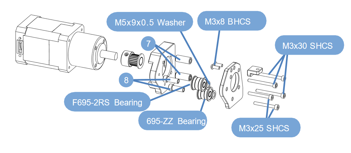
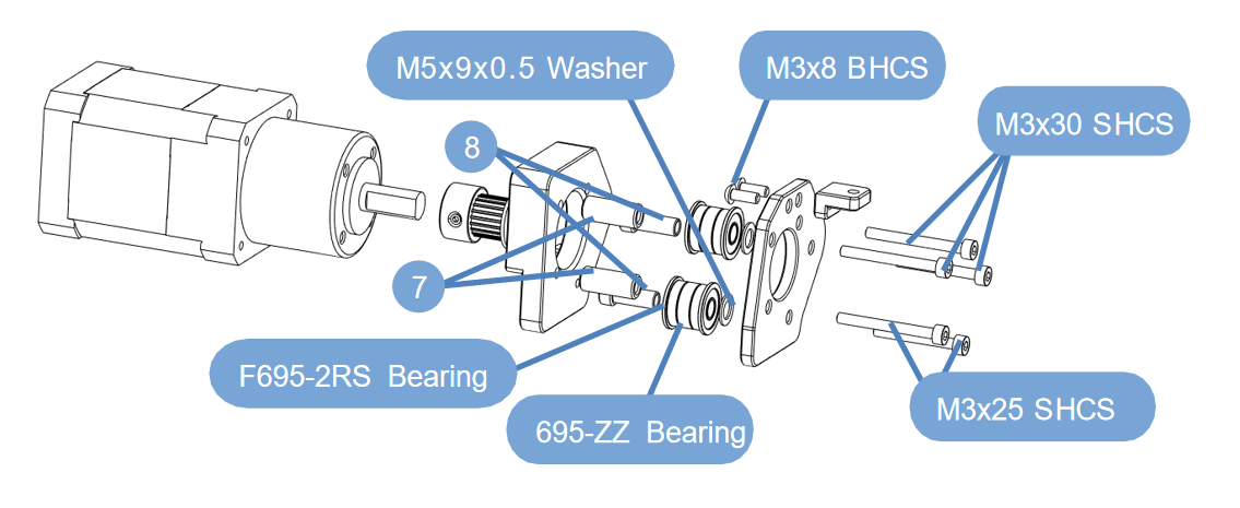
- Material preparation
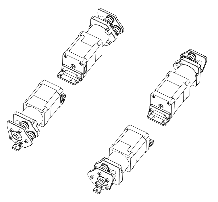
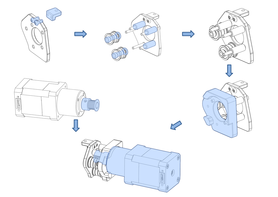
Z motor assembly-Right
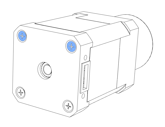
- First remove the two screws on the motor tailstock,Note the location of the removed screws.
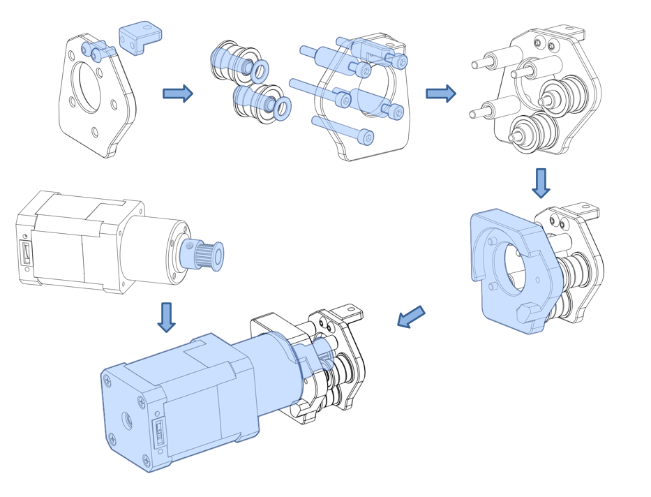
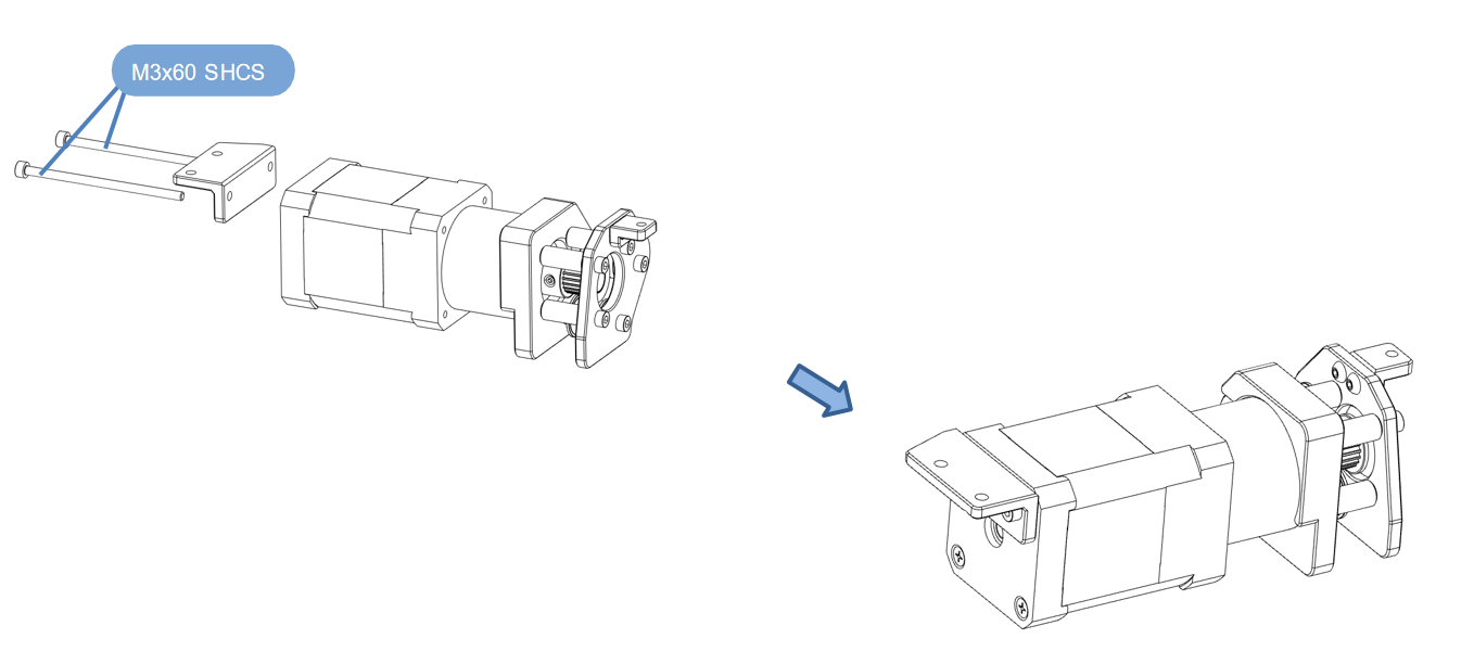
- Take out the Z-axis motor and the corresponding machined parts, pay attention to distinguish the left and right, and assemble them according to the diagram.. Quantity: 2 pcs.Assemble the accessories according to the following figure.
Z motor assembly-Lift
- First remove the two screws on the motor tailstock,Note the location of the removed screws.
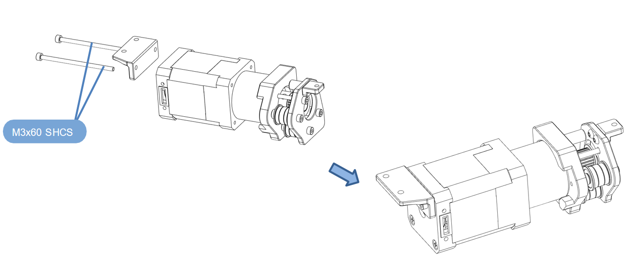
- Take out the Z-axis motor and the corresponding machined parts, pay attention to distinguish the left and right, and assemble them according to the diagram.. Quantity: 2 pcs.Assemble the accessories according to the following figure.
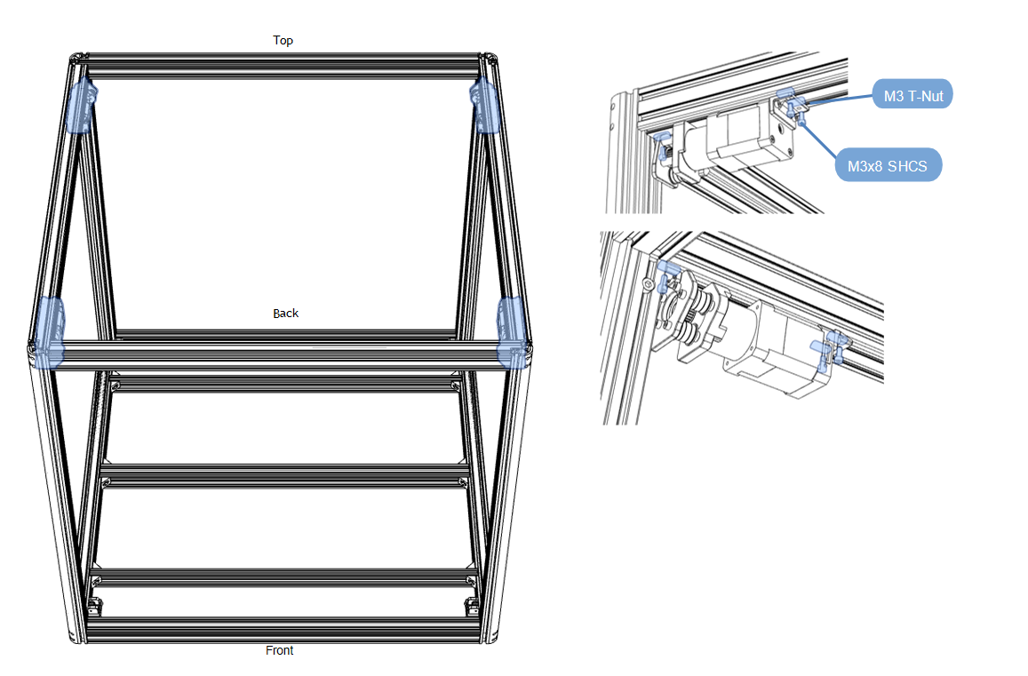
Z motor assembly installation
- lace the Z-axis motor assembly on top of the profile frame, flush with the upper surface of the profile, pay attention to distinguish between left and right, Assemble as shown in the figure. Quantity: left x2, right x2, diagonally the same. Pay attention to the idling direction. The motor and the idler wheel must be consistent.
Z motor line installation
- Install the motor wires according to the arrows in the figure.
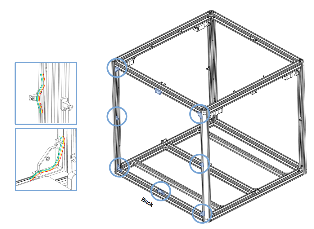
- Place the motor wires in the slot and cover them with aluminum profile slot seals.
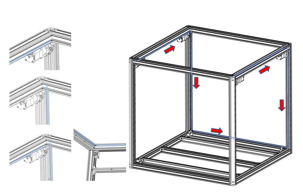
NOTE: When installing the motor wires, you need to reserve space for the acrylic plate corner pieces, otherwise you will need to take out the motor wires later.
- When installing the motor wires, you need to reserve the position marked in the figure.
This chapter is assembled
Previous
2.1 Frame assembly
Next
2.3 Gantry components
Last modified: 2025-07-31
Outline