FLASHFORGE_AD5X Enclosure Kit
AD5X Installation Guide
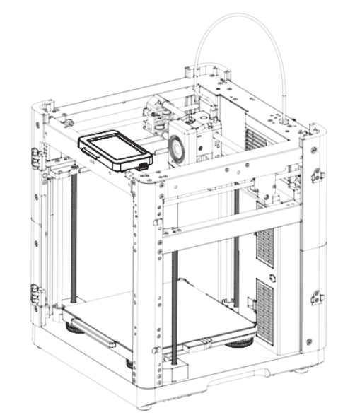
1. Product Introduction
- Product outline drawing
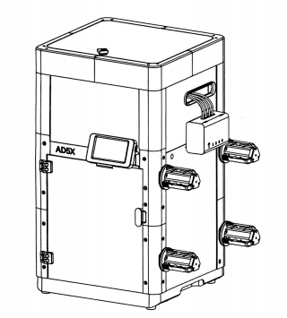
2. Applicable machine:
AD5X
This Guide is only applicable to FLASHFORGE AD5X 3D printer.
3. Accessory Package Contents and Parts list
①. List of Accessory Package Contents:
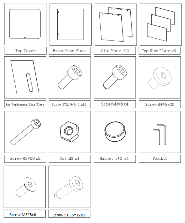
Friendly Reminder: Please prepare 2.0mm and 2.5mm Allen wrenches, and a Phillips screwdriver for installation. As screw types may vary, please select tools according to the actual screws.
Note: Due to possible variations or differences in screw types, the actual accessories may differ from the images. Please refer to the actual accessories.
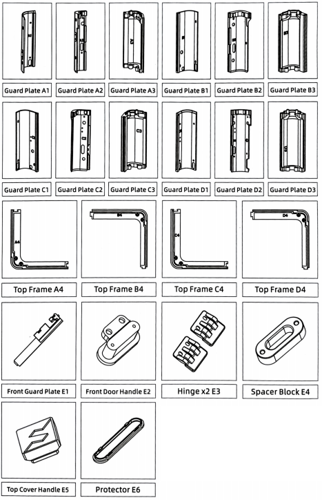
②. Parts List:
-
Printable document download link:

Note
①.Download the listed parts from to print them. (here ) or Scan the QR code above.
②.Guard plates with markings inside.
4. Installation video
- You can watch the assembly video.
5. Assembly steps
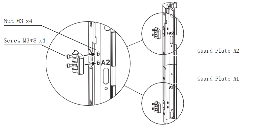
Step 1 Install Hinges
-
Assemble the guard plates A1 and A2.
-
Insert four M3 nuts into the embedded slots of the guard plates. Then, use two M3*8 screws for each hinge to secure the upper and lower hinges onto the guard plates.
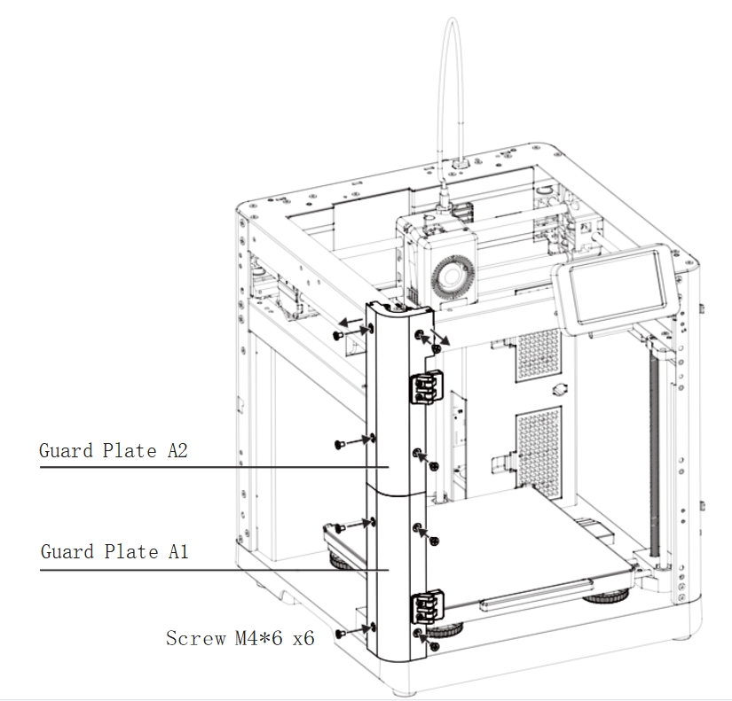
Step 2 Install Guard Plates A1 and A2
-
As shown in the image, remove the top two M4*6 screws from the machine.
-
Install the assembled guard plates A1 and A2 with hinges installed, and lock them. Then, secure the remaining mounting holes with six M4*6 screws.
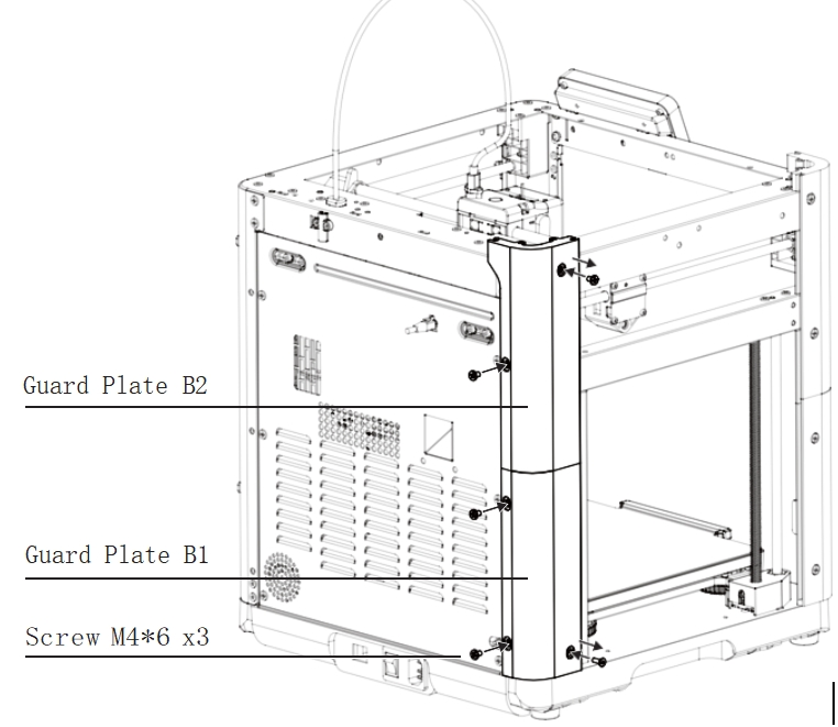
Step 3 Install Guard Plates B1 and B2
-
Assemble the guard plates B1 and B2.
-
Remove the upper and lower screws from the left rear side of the machine.
-
Install the assembled guard plates B1 and B2, and lock them. Then, secure the back with three M4*6 screws.
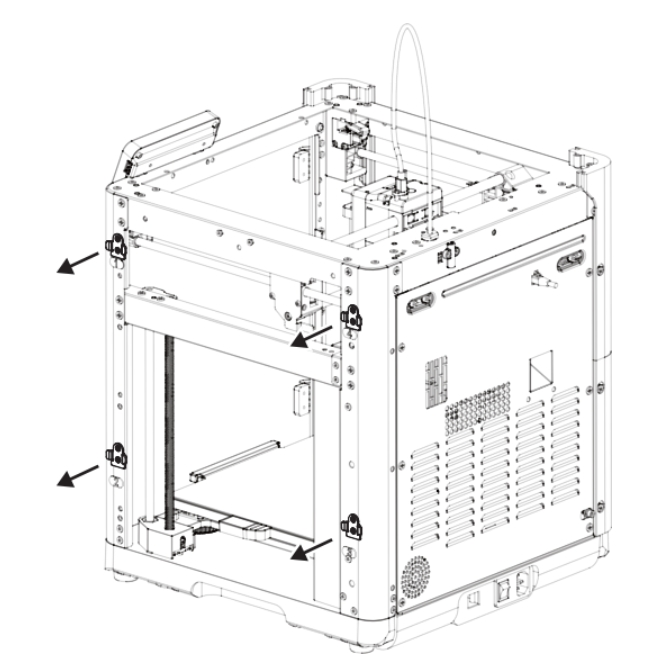
Step 4 Remove Spool Holder Clips
-
Remove the spool holder clips from positions 1, 2, 3, and 4 on the right side of the machine and place them neatly on a table.
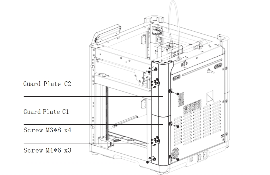
Step 5 Install Guard Plates C1 and C2
-
Assemble the guard plates C1 and C2.
-
Remove the upper and lower screws from the right rear side of the machine, install the assembled guard plates C1 and C2, and lock them. Then, secure the back with three M4*6 screws.
-
Place two spool holder clips on the sides of guard plates C1 and C2, and secure each with two M3*8 countersunk screws. (Ensure the rounded side faces up and the hooks face outward.)
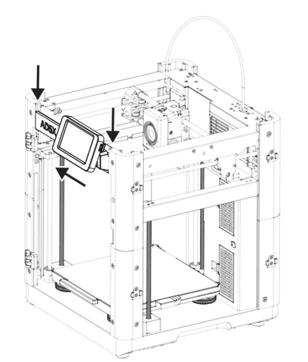
Step 6 Remove the Display Screen
-
Hold the display screen with your hand and gently slide it to the right to detach it from the sliding clip.
-
Without disconnecting the screen cable, place the display screen along with the cable on the front top metal beam.
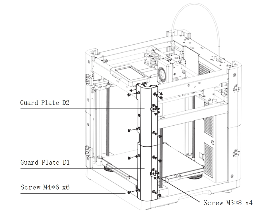
Step 7 Install Guard Plates D1 and D2
-
Assemble the guard plates D1 and D2.
-
Remove the top two M46 screws from the machine, install the assembled guard plates D1 and D2, and lock them. Then, secure the lower part with six M46 screws.
-
Place two spool holder clips on the sides of guard plates D1 and D2, and secure each with two M3*8 countersunk screws. (Ensure the rounded side faces up and the hooks face outward.)
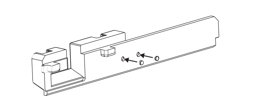
Step 8 Install Magnets into Guard Plate E1
-
Apply a small amount of instant adhesive to the two holes in the guard plate E1 and press two magnets into the holes.
Step 9 Install the Guard Plate E1 and Display Screen
-
Slide the screen cable into the slot on the guard plate E1, fold the cable so that it is positioned horizontally, and hold the screen in place.
-
Insert the guard plate E1, along with the display screen, downward into the slots at the top of the guard plates A2 and D2 until it reaches the bottom.
-
Finally, slide the display screen from right to left into the horizontal slot on the guard plate E1.
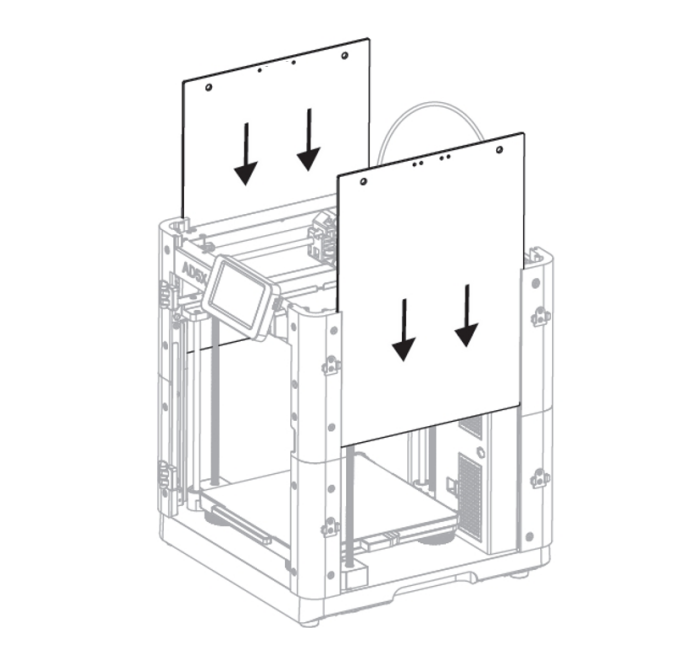
Step 10 Install Acrylic Side Plates
- Slide the two acrylic side plates into the side slots of the guard plates A2, B2, C2, and D2 until they reach the bottom of the slots.
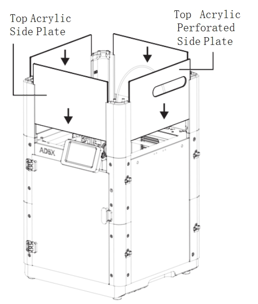
Note
The side panel is divided into left and right sides, and an acrylic board with two additional holes is installed on the right side, on the same side as IFS
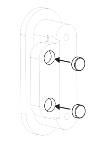
Step 11 Install Magnets into Front Door Handle E2
-
Apply a small amount of instant adhesive to the holes in the front door handle E2 and press two magnets into the holes.
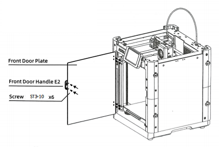
Step 12 Install the Front Door Plate and Front Door Handle E2
-
Secure the front door handle E2 to the front door plate using two ST3*10 screws.
-
Attach the front door plate to the hinges using four ST3*10 screws.
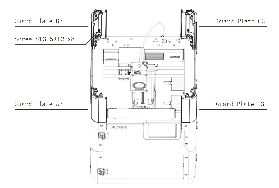
Step 13 Install Guard Plates A3, B3, C3, and D3
-
Secure the guard plates A3, B3, C3, and D3 to the top of the guard plates A2, B2, C2, and D2 using two ST3.5*12 screws for each plate.
Step 14 Install Top Acrylic Side Plates
-
The sides of the guard plates A3, B3, C3, and D3 have slots designed for installing the top acrylic plates.
-
Slide the three top acrylic side plates into the front, rear, and left slots until they reach the bottom.
-
Slide the top acrylic perforated side plate into the right slot with the hole facing the rear of the machine until it reaches the bottom.
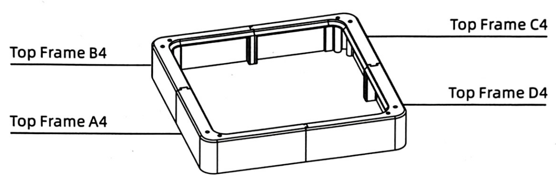
Step 15 Install Top Frames A4, B4, C4, and D4
-
Assemble the top frames A4, B4, C4, and D4 in sequence, aligning the grooves from top to bottom with the corresponding protrusions.
-
Gently tap the top surface to ensure the entire frame is level.
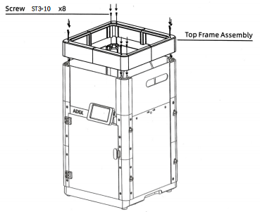
Step 16 Install the Top Frame Assembly
-
Align and insert the top frame assembly (A4, B4, C4, D4) from top to bottom into A3, B3, C3, and D3.
-
Ensure all acrylic plates are fully seated within the top frame slots, and then secure with eight ST3*10 screws.
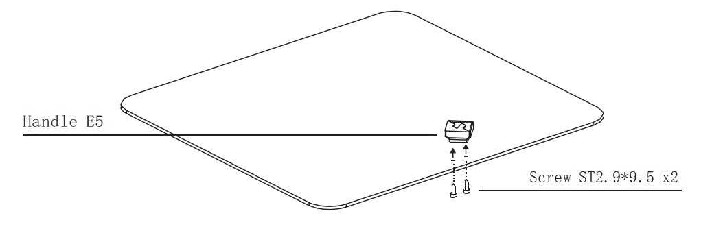
Step 17 Install the Top Cover Assembly
-
Secure the handle E5 to the acrylic top cover using two ST2.9*9.5 screws.
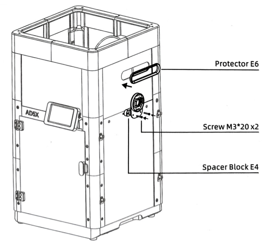
Step 18 Install the Protector E6 and IFS Mounting Plate
-
Snap the protector E6 into the hole in the top acrylic plate.
-
Align the spacer block E4 with the IFS mounting plate and secure them together using two M3*20 screws, fastening them into the threaded holes on the right side of the machine.
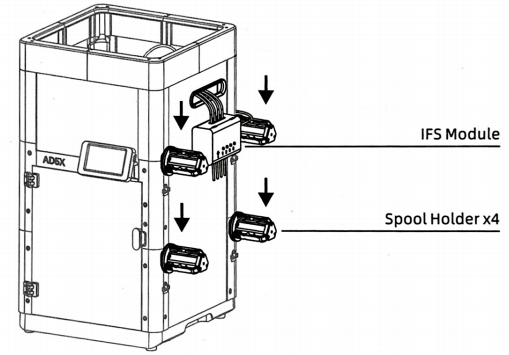
Step 19 Install Spool Holders and IFS Module
-
Align the four spool holders with the metal clips on the right side of the machine and insert them downward until fully seated.
-
Place the IFS module into the circular retaining ring, with the arrow pointing at the 10 o'clock position. Rotate it clockwise until it clicks into place, ensuring the arrow points upward.
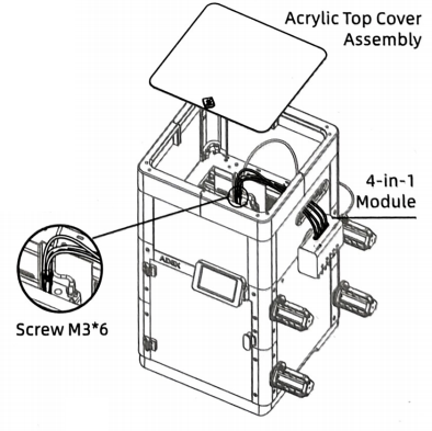
Step 20 Install the 4-in-1 Module and Acrylic Top Cover Assembly
-
Insert the four guide tubes of the 4-in-1 module into the four channels of the IFS module until fully seated.
-
Pass the end of the 4-in-1 module through the hole in the right-side top acrylic plate, and then insert the stainless steel tube into the hole of the extruder assembly. Install it all the way down, and then gently pull upward to ensure it's secure.
-
Install the acrylic top cover assembly.
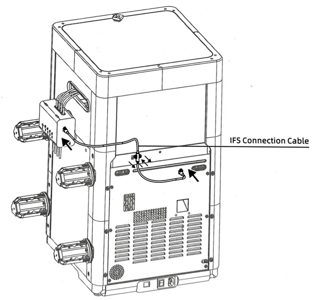
Step 21 Install the IFS Connection Cable and Cable Clip
-
Remove the two M3*4 screws from the cable clip at the rear of the machine.
-
Insert both ends of the IFS connection cable into the ports on the IFS module and the printer respectively.
-
Secure the cable with the cable clip and tighten the screws.
6. FAQ
- Q: How to install to my 3D printer? A: You can watch the assembly video.
- Q:Does the installation require additional printed fixtures? A:Not needed
7. Shop
8. Tech Support
facebook group:https://www.facebook.com/groups/197476557529090/
Tech Support Email: hunter@fysetc.com
Forum:https://forum.fysetc.com/